PATTERN INTERFERENCE
IN FRICTION RIDGE
IMPRESSIONS
Regarding the Analysis phase of the ACE-V methodology,
a wide variety of distortion mechanisms must be understood. One particular example of distortion is
pattern interference. This interference results from multiple
impressions of latent friction ridges superimposed, in whole or in part, on one another. (Figure 1) The interference pattern of these impressions can be from
the combination of the same or different areas of friction skin. It is very important to understand the
various features of pattern interference.

Figure 1.
Interference
features occur as the result of two or more overlying or superimposed
fingerprint impressions, or as the result of slight linear and/or angular
movement during the deposition of a single latent print impression. In the latter, the flexibility of the
epidermis under the influence of non-perpendicular forces at the moment of
latent deposition is often the source of the non-alignment. In many aspects, latent print
impressions can be thought of as a static wave. These interference patterns, also called moiré patterns,
have several aspects that are related to the basic physics of two-source wave type interference. The main differences are that, in
general, physical frequencies, such as water waves, are repetitious generic
amplitudes, whereas, each latent ridge contains unique information in its
static structure. In addition,
along any particular axis within a print impression, the frequency of the
ridges, or their relative spacing and direction, will vary to some degree due
to the unique shape of a fingerprint. Ultimately, we are concerned with how this information
changes at the constructive and destructive like interference positions that
result from non-aligned superimposed latent friction skin impressions. What is found is that, unique ridge
structure information cannot be compounded in a constructive manner. Not only would some information
be lost to the interference, some new non-relevant information would likely be
gained.
Specifically,
interference patterns are caused by like patterns types occupying particular
spatial relationships to one another.
With overlapping friction skin impressions, multiple interference
patterns can be produced at various angles. These visual interference geometries will be found at
different levels of prominence depending on the shape of each print and the
amount of relative difference or offset.
If an overlapping print is just slightly offset in a linear manner, a
few interference patterns are seen.
If an angular displacement is added, additional interference patterns
will be seen with a degree that is related to the relevant relationships of
overlapping ridges.
The following two
examples of superimposed inked print impression show both linear and angular
rotational pattern features. In
the left example of Figure 2, the top print is offset to the right by about 1/2
ridge width. The most notable
interference is found in the vertical ridges. In the right example of Figure 2, an additional counter
clockwise rotation was added to show the additional associated curved
patterns. Note that with the
additional angular displacement in the right print, the interference pattern
left of the print’s core is not the same as the pattern found in the left print
even though they both had the same right linear displacement. As the top print was rotated the ridges
in this area changed their spatial relationship. Also, on the right most print, note the epicenter just
above the core around which the rotation occurred. In most cases, a superimposed print will not rotate so
neatly around a center point.
Since the ridges above the epicenter are also semi-circular, the apparent distortion is at a minimum as
the ridges were superimposed in a more precise alignment. Ridges perpendicular to the
displacement often show the greatest amount of interference as they are
displaced the most relative to other areas of the impression.

Figure 2
The visual
features where the patterns are at a point of focus are called a node. A linear series of nodes along an axis
are described as nodal positions or locations. This nodal axis may be straight or curved. Specifically, nodal positions are
locations within the distortion area where interference is at maximum and
minimum levels. Anti-nodal positions are where the
interference is found to be at a maximum destructive level and nodal positions are locations where the visual interference is at a minimum, [1]
or in some cases, an undisturbed state.
See Figure 3. Along the
nodal axis, two ridges may precisely overly each other. As previously noted, we would expect
some loss of information when regarding the unique information contained within
the friction ridges in such a relative state. As the particular physics of two-wave source pattern
interference is not entirely compatible with the unique attributes of friction
skin, and other unique types of pattern sources such as shoe and tire
impressions. Accordingly, we need
to understand that the areas of interference can only be described accurately
with the terms Nodal and Anti-Nodal. In our comparative
forensic science cases, these terms do not necessarily imply the value or
quality levels of the information contained within the friction ridges but
rather their apparent displacement.
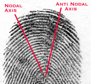
Example of minimum
(Nodal) and maximum (Anti-Nodal) interference.
Figure 3
The offsets of the
various impressions are most likely found in two dimensions, and of varying
degrees. As noted earlier,
both linear
and angular displacements must be considered, as well as the specific
variability in the impression’s frequency or ridges spacing. This can often be equivalent to our
latent print lateral and circular slippage. [2] This variability of ridge spacing
will be relevant to the specifics of the deposition itself, due again to the
flexibility of the epidermis and the variance of the substrate. Slight changes in ridge spacing due to
a compression or extension, will accordingly, generate a specific interference
pattern locally, and will be visualized as a variation in both the nodal and
anti-nodal axis. The direct
relationship between ridge frequencies and a difference in their expected
interference pattern appears to be mathematically proportional in symmetry,
meaning that a slight difference in displacement will yield a slight
modification in the axis of the interference pattern.

Figure 4
In
figure 4 compare the anti-nodal axis locations on the latent print on the left,
with the interference patterns on the recreation
print on the right. The recreation
print was made with two exemplars.
The superimposed second impression was offset and rotated several
degrees counter clockwise. Note
that the left registration mark (in the upper right corner) is the second
impression. While the recreation
composite is not a precise match, it does illustrate the interference mechanism
and principle and illustrates that the distortion can be understood on a
scientific level.
It is important to
understand that a superimposed print that is sufficiently offset in its
alignment with the first impression may
not accurately represent the spatial relationship of minutia of either
print. This is especially true
when considering third level details.
This combination can create a new set of characteristics, or a combination
of information from each impression, that may
or may not be visually separable.
Also, it is noted that the “ridges furthest from the epicenter of
rotation (angular displacement) … undergo a greater linear displacement than
those nearer the center.” [3] See figure 2. Thus, as related to fingerprint individualization, the nodal
and anti-nodal axis’ simply represents an offset of ridges in relationship to
the impression’s frequency or ridge spacing, and not necessarily a division of
the quality of information into good and bad categories. Or in other words, the most apparent
visual interference at the anti-nodal locations may degrade the quality of the
information just as much as the nodal positions. In many cases the seemingly clear areas along the nodal
axis, are produced by different
ridges, or ridge sections overlying each other. The examiner will have to critically analyze the impression
to understand the composition of the overlay, its degree of distortion, and
subsequently the value of the information available for comparison.

Figure 5
In figure 5 the
superimposed second impression is registered just one ridge off down to the
left. New information is created
in the process, yet the original characteristics are not entirely canceled
out. In this case, Karen Hare’s Proportional Analysis concept is
beneficial in understanding the true relationships of the information. [4]
The analysis stage of the ACE-V process is a
fundamental inventory of available informational components to be used in a
comparison. This information is
analyzed for its quantitative and qualitative aspects, as well as its
specificity and relevance.
With analysis being one of the most difficult and variable aspects of
the ACE-V, it is critical to fully comprehend the specific makeup of a latent
print’s distortion as this will, in turn, help the examiner to better
understand the value of the information available. Displacement pattern interference, which is represented as
nodals and anti-nodals, are dependent on the periodic and non-periodic aspects
of the friction skin relative to the angular and rotation aspects of the
subsequent impression. A careful
analysis of the interference and the pattern it creates, will help reveal the
level of distortion and subsequently the value of the friction skin
impression. For a subtle example of pattern interference in the form caused by localized slippage also reference: SWGFAST Document #10 Standards for Examining Friction Ridge
Impressions and Resulting Conclusions (Latent/Tenprint) Appendix B Figure B5.
Training Exercise:
To create your own
visual display of interference patterns in action, scan one loop and one plain
whorl pattern in Adobe Photoshop following the simple guide below, repeating
for the different pattern. Follow the instructions below for each loop and whorl pattern.
1. With Adobe Photoshop, Scan a grayscale
print at a good resolution.
600dpi
or more.
2. Duplicate the main layer. (right mouse click and select:
duplicate copy layer)
3. Turn off the background layer for now.
4. Using the magic wand, with a tolerance
of about 50. Delete the background
from
the new layer. All you want is a
skeleton of a print. It may help
to
drop a colored
background under your working layer, such as red. This will ensure you have delete all the background.
5. Add
a small [circle] registration mark in the corner of your main background print.
6. Add
a small [plus] registration mark on your skeletonized print layer, directly
over the circle as seen on the main background layer. (SAVE)
7. With
the colored layer off or deleted, and both [print] layers turned on, use your
“move” tool and rotate the skeletonized print layer to offset the two prints
relative to each other.
a. Note
how the interference patterns change relative to each prints linear and angular
displacement.
Craig A. Coppock CLPE
20071104 High Resolution Images are available upon request.
Updated: 20170326
Updated: 20170326
References:
1. Glenbrook South Physics Teachers Home
Page, Two-point interference pattern.
Home
Page
www.glenbrook.k12.il.us/gbssci/phys/phys.html
Two
Point interference patterns.
www.glenbrook.k12.il.us/GBSSCI/PHYS/CLASS/light/u12l1b.html
2. Wertheim, Pat Analysis of Problem
Latents & Ridgeology Comparison Techniques
(19 tools) Specifically: Lateral and Circular
slippage.
3. Cowger, James: Friction Ridge Skin;
Comparison and Identification of Fingerprints.
Elsevier,
1983 New York, p 187
4. Hare, Karen (Midland Texas Police
Department) Author of Proportional Analysis
(in comparative forensic science)
This article posted to: http://fingerprintindividualization.blogspot.com
This article posted to: http://fingerprintindividualization.blogspot.com
No comments:
Post a Comment